


Views: 0 Author: Site Editor Publish Time: 2026-08-14 Origin: Site


Poorly specified material handling systems carry severe hidden operational penalties. Unplanned downtime, severe product degradation, and hazardous dust exposure routinely erode facility efficiency. Moving powders, granules, and lumpy solids presents complex engineering challenges. Material behavior shifts unpredictably under changing pressure, ambient humidity, and motion. This renders one-size-fits-all machinery entirely ineffective. Facilities that fail to account for these variables face constant maintenance interventions and compromised product quality.
Establishing a strict framework for evaluating and selecting the right bulk solids handling equipment requires detailed material characterization and a clear understanding of facility constraints. You must align mechanical and pneumatic technologies with the specific flow properties of your product. This guide breaks down the core categories of handling equipment, establishes strict evaluation criteria, and provides actionable strategies to mitigate common flow interruptions and safety risks in industrial processing environments.
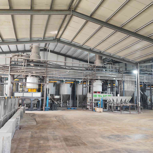
Material characterization (bulk density, flowability, abrasiveness, moisture sensitivity) must dictate equipment selection before calculating throughput requirements.
Distinct handling stages—storage, conveying, metering, conditioning, and packaging—require specialized technologies with specific operational and maintenance trade-offs.
Compliance with safety standards (e.g., combustible dust regulations, food-grade sanitation) is a non-negotiable baseline that heavily influences system design and footprint.
Table of Contents
Successful system design begins in the laboratory. Assuming a material will flow based purely on visual inspection leads to catastrophic equipment failures. You must quantify the physical properties of the bulk solid under the exact conditions it will experience during processing. Engineers rely on empirical data to size hoppers, select conveyor types, and specify feeder geometries.
Baseline material testing dictates every downstream engineering decision. Cohesiveness measures the tendency of particles to bind together under pressure. This metric directly influences hopper wall angles and discharge opening dimensions. The angle of repose indicates how a material forms a pile when dropped onto a flat surface. This angle affects silo storage capacity and the placement of level sensors. Bulk density determines the volumetric capacity required for storage and conveying systems.
You must measure both aerated bulk density and packed bulk density. Materials compress during storage in tall silos and expand during pneumatic transport or fluidization. Designing a volumetric feeder based on aerated density will result in severe overfeeding if the material settles and packs inside the supply hopper. Particle size distribution (PSD) dictates the selection of filtration systems and helps predict segregation risks when handling blends of fine powders and coarse granules. A wide PSD often leads to finer particles sifting through the voids between larger particles during transport.
Bulk solids react dynamically to their surrounding environment. Ambient humidity rapidly alters the flowability of hygroscopic materials. Powders that flow freely in a dry winter environment may clump, bridge, and block discharge openings during humid summer months. Temperature sensitivity requires careful evaluation. Materials with low melting points, such as resin pellets or fat-filled dairy powders, can smear or degrade when exposed to the friction generated by high-speed mechanical conveyors or rotary valves.
Aeration introduced during pneumatic conveying or fluidization changes the material's internal friction. This temporarily transforms heavy powders into fluid-like states. Highly aerated powders easily flush through rotary valves and screw feeders, bypassing metering controls and flooding downstream processes. You must design hoppers with sufficient residence time to allow these powders to de-aerate before they reach the feeding mechanism.
You must establish measurable operational goals before reviewing equipment specifications. Determine if the process requires mass flow or if funnel flow is acceptable. In a mass flow regime, all material in a vessel moves simultaneously during discharge. This eliminates stagnant zones, prevents spoilage of perishable goods, and provides a first-in-first-out (FIFO) discharge pattern. Funnel flow allows active movement only in a central channel above the discharge opening, leaving stagnant material packed against the vessel walls.
If handling blended products, success means preventing particle segregation during transfer and storage. For batching operations, define the required accuracy tolerances. Achieving a feed accuracy of plus or minus one percent requires entirely different metering technology than a process allowing a five percent variance. High-accuracy batching typically demands gravimetric feeding systems integrated with fast-acting slide gates and precision load cells.
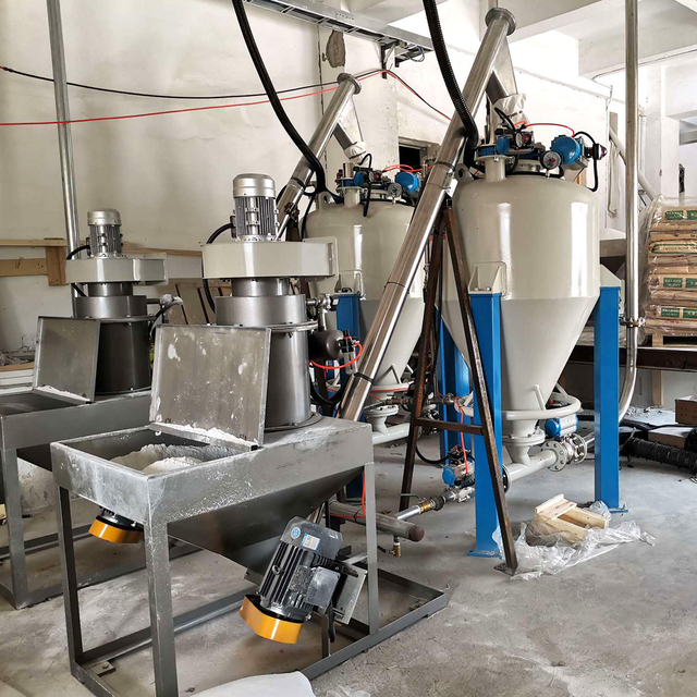
Industrial processing relies on a sequence of specialized machinery to move raw materials from delivery to final packaging. Each category serves a distinct function and requires specific design considerations to maintain process reliability and minimize operator intervention.
Storage vessels buffer production lines and house raw materials. Silos provide high-capacity, long-term storage and are typically located outdoors. They are constructed from bolted or welded carbon steel, stainless steel, or aluminum. Hoppers are smaller, intermediate vessels positioned directly above process equipment to maintain a continuous supply of material. Day bins hold exactly one shift or one day's worth of production volume, isolating the active process from bulk storage.
Geometric design principles govern the reliability of these vessels. Conical hoppers require steeper wall angles to promote flow compared to wedge-shaped or chisel hoppers. The discharge opening must be large enough to overcome the material's cohesive strength, preventing arching and ratholing. Engineers use shear cell testing data to calculate the exact wall friction angles and outlet dimensions required to achieve reliable mass flow. In some cases, applying ultra-high molecular weight (UHMW) polyethylene liners to the internal walls reduces friction enough to convert a funnel flow hopper into a mass flow hopper.
Moving materials horizontally, vertically, or at an incline requires selecting between mechanical and pneumatic transport methods based on distance, volume, and material fragility.
Troughed belt conveyors: Ideal for moving high volumes of abrasive or coarse materials over long distances. They offer high capacity and low power consumption per ton but require significant floor space and are difficult to completely enclose for dust control.
Drag chain conveyors: Utilize a continuous chain with attached paddles to drag material through an enclosed trough. They are excellent for handling hot, abrasive, or sluggish materials and provide complete dust containment.
Screw conveyors: Use a rotating helical flight inside a tube or U-trough to push material forward. They are highly versatile, can operate at inclines, and allow for multiple inlet and discharge points.
Bucket elevators: Provide efficient vertical lifting for free-flowing granules and pellets. Centrifugal discharge elevators operate at higher speeds to throw material into the discharge chute, while continuous discharge elevators operate slowly to gently spill fragile materials into the chute.
Pneumatic conveying systems utilize air or inert gas to transport powders through enclosed pipelines, offering excellent dust containment and flexible routing around existing facility infrastructure.
Dilute phase conveying: Operates at high velocities and low pressures. Particles are fully suspended in the airstream. It is highly effective for non-abrasive powders but can cause severe degradation to fragile materials and rapid wear on pipelines when handling abrasives.
Dense phase conveying: Operates at low velocities and high pressures. Material moves in distinct slugs or a continuous moving bed along the bottom of the pipe. It protects friable materials, minimizes pipeline erosion, and prevents blended materials from segregating during transport.
Conveying Technology Comparison
Technology Type | Best Suited For | Primary Advantages | Key Limitations |
|---|---|---|---|
Troughed Belt Conveyor | High-volume, coarse, abrasive aggregates | High capacity, low power consumption per ton | Large footprint, difficult to contain dust |
Drag Chain Conveyor | Hot, sluggish, or highly abrasive solids | Fully enclosed, handles extreme temperatures | High mechanical wear on chain links and sprockets |
Bucket Elevator | Vertical lifting of free-flowing granules | Minimal horizontal footprint, high lift capability | Difficult to clean, risk of material cross-contamination |
Dilute Phase Pneumatic | Non-abrasive, non-fragile powders | Flexible routing, complete dust containment | High particle attrition, pipeline wear with abrasives |
Dense Phase Pneumatic | Friable, highly abrasive, or blended solids | Gentle handling, low pipeline wear, prevents segregation | Requires heavy-duty compressed air infrastructure |
Process integration demands precise control over the rate at which material enters downstream equipment. Volumetric feeders discharge a consistent volume of material per revolution or cycle. They are simple and reliable but cannot detect changes in material bulk density. Gravimetric feeders, such as loss-in-weight (LIW) systems, continuously weigh the discharging material and adjust the mechanical drive speed to maintain a precise mass flow rate. This compensates for density fluctuations and ensures strict batch accuracy.
Rotary valves act as both airlocks and volumetric feeders. They transfer powders between environments with different pressure profiles, such as feeding material into a pressurized pneumatic conveying line. Screw feeders utilize rotating augers to draw material from hoppers. Varying the pitch of the screw or using a stepped shaft ensures even withdrawal across the entire hopper outlet, preventing stagnant zones. Vibratory feeders use electromagnetic drives to move fragile or lumpy materials gently along a pan. Weigh belts continuously measure the mass of material traveling across a conveyor section, making them ideal for high-capacity continuous batching of aggregates or minerals.
Materials often require preparation before entering the main process. Inline conditioning equipment protects downstream machinery and ensures product consistency. Lump breakers utilize rotating blades or crushing rollers to reduce agglomerations that form during storage or transit. This restores powders to their original particle size and prevents blockages in rotary valves. Vibratory screeners classify materials by size, removing oversized contaminants, unblended clumps, and fine dust.
Magnetic separators extract ferrous tramp metal from the product stream. Grate magnets sit inside hopper throats to catch fine metal shavings, while heavy-duty plate magnets suspend over belt conveyors to pull large bolts or tools out of the material bed. Removing tramp metal prevents catastrophic damage to downstream mills, extruders, and rotary valve rotors.
Initiating flow from storage often requires mechanical assistance. Bin activators are vibratory cones attached to the bottom of silos that break material bridges and promote even drawdown. Fluidization pads inject low-pressure air into the boundary layer between the powder and the hopper wall. This reduces wall friction and allows aeratable powders to flow freely. Mechanical agitators use rotating sweeps to physically dislodge cohesive materials that resist gravity discharge.
End-of-line systems transition bulk materials into transportable formats. Bulk bag (FIBC) unloaders safely suspend and discharge super sacks. They often incorporate massage paddles to break up compacted material and untie boxes to protect operators from dust exposure. Bulk bag fillers utilize inflatable seals and densification tables to maximize the amount of product packed into each bag, stabilizing the load for transport. Bagging scales automate the filling of smaller 25-kg valve or open-mouth bags, integrating directly with robotic palletizing systems for complete end-of-line automation.
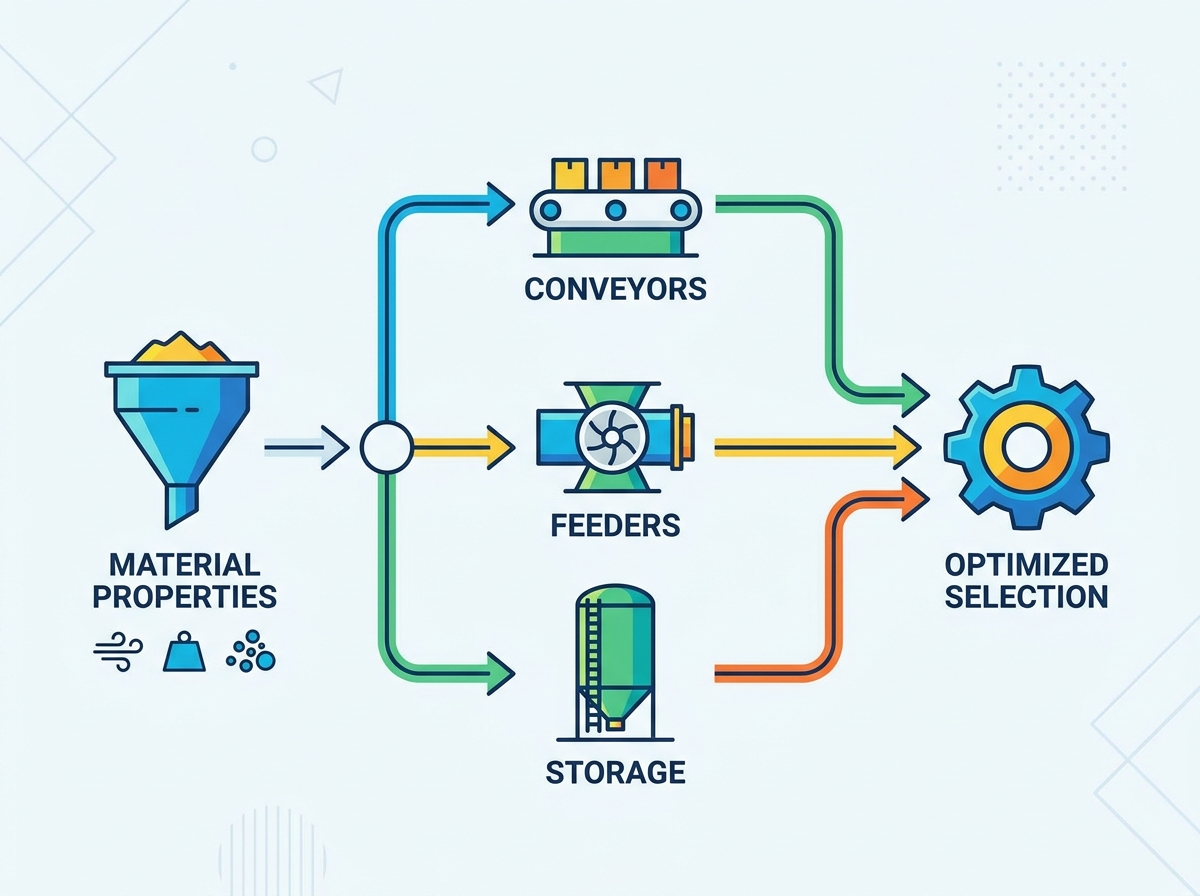
Selecting the correct machinery requires balancing theoretical capacity against the physical realities of the production facility. Equipment must integrate directly into existing control architectures while adhering to stringent safety regulations and spatial limitations.
Calculating required tons-per-hour (TPH) is only the first step. You must balance this throughput against available vertical clearance and horizontal floor space. High-capacity mechanical conveyors demand significant linear space, while bucket elevators require substantial vertical headroom for drive assemblies and discharge chutes. Interacting variables complicate these calculations. Dynamic bulk density changes under compression mean that a volumetric feeder sized for aerated powder will severely underperform if the material settles and densifies in the supply hopper. Engineers must size equipment based on the worst-case flow scenarios, not just ideal laboratory conditions.
When retrofitting existing facilities, spatial constraints often dictate the technology selection. A steep incline conveyor with corrugated sidewalls can elevate materials at 90-degree angles, bypassing the need for the long horizontal runs required by standard troughed belts. Pneumatic conveying lines can route vertically through floors and around structural columns, offering maximum layout flexibility in tight spaces.
Modern bulk solids handling relies heavily on automated control. Equipment must accommodate load cells for continuous weight monitoring and level sensors to prevent silo overfilling. Radar, ultrasonic, and capacitance probes provide real-time inventory data to the central control room. Variable frequency drives (VFDs) are mandatory for feeders and conveyors, allowing operators to fine-tune discharge rates and ramp equipment up or down smoothly.
This hardware must communicate directly with existing SCADA or PLC networks. Specify communication protocols like Ethernet/IP, PROFINET, or Modbus early in the design phase. This ensures the mechanical systems can execute automated batching recipes, trigger alarms for flow interruptions, and initiate shutdown sequences without manual operator intervention.
Safety and sanitation standards dictate specific equipment features. When handling combustible dusts, systems must adhere to ATEX or NFPA standards. This requires installing explosion vents to direct deflagration pressure safely outdoors. You must integrate chemical suppression systems and mechanical isolation valves to prevent flames from propagating through pneumatic pipelines into connected vessels. Equipment must be properly grounded and bonded to dissipate static electricity, which serves as a primary ignition source for dust clouds.
In food, dairy, and pharmaceutical applications, FDA and USDA requirements mandate sanitary, wash-down environments. Equipment must feature continuous TIG welds, polished stainless steel contact surfaces, and the complete elimination of internal crevices where bacteria can harbor. Bearings and drive components must be isolated from the product zone to prevent lubricant contamination.
Procurement decisions based solely on initial specifications often ignore the long-term realities of running a facility. Evaluating the true impact of a system requires analyzing energy usage, maintenance demands, and future adaptability.
Mechanical conveying systems generally utilize fractional or low-horsepower motors, resulting in highly efficient energy profiles. However, mechanical systems rely on hundreds of moving parts—bearings, belts, chains, and buckets—that require constant lubrication, tensioning, and replacement. Abrasive materials rapidly destroy mechanical wear parts, driving up maintenance labor and replacement frequency.
Conversely, pneumatic systems require massive industrial blowers or compressors to generate the necessary air volume and pressure. They consume significant electrical energy continuously during operation. However, pneumatic systems have very few moving parts in contact with the material. You must weigh the heavy energy demands of pneumatic transport against the intensive mechanical wear-part replacement cycles of belt and bucket systems.
Downtime for cleaning and maintenance represents a massive operational penalty. Equipment designed with quick-release clamps, slide-out rotor rails, and accessible inspection hatches allows maintenance teams to perform sanitation cycles in minutes rather than hours. Clean-in-place (CIP) capabilities utilize integrated spray nozzles to wash internal components without disassembly, drastically reducing manual labor.
Fully enclosed, hard-to-reach systems will paralyze production schedules during product changeovers or routine maintenance interventions. If operators must unbolt heavy flanges or enter confined spaces to clean a rotary valve, the facility will suffer severe productivity losses. Prioritize tool-less entry and cantilevered drive shafts that allow operators to slide internal components out for rapid inspection.
Facility output rarely remains static. Over-engineering a system for theoretical future capacity ties up resources and often causes equipment to run inefficiently at lower current throughputs. A pneumatic conveying line sized for 50 TPH will experience severe particle degradation and pipeline wear if run at only 10 TPH due to incorrect air-to-cloth ratios and excessive velocities.
Instead, design modular systems. Specify conveyors with bolted frame extensions that can be lengthened later. Select feeders with interchangeable screw profiles to handle different materials as product lines evolve. Install pneumatic pipelines sized to accommodate larger blowers in the future. Modular flexibility allows you to scale production capacity incrementally, aligning equipment upgrades directly with facility growth.
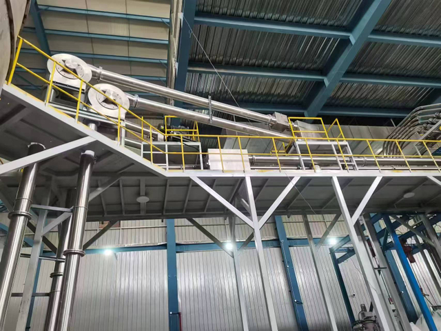
Even properly specified equipment encounters operational challenges when material properties fluctuate due to weather or supplier changes. Anticipating these failure modes allows you to integrate mitigation strategies directly into the system design.
Bridging occurs when particles interlock over the discharge opening, forming a structural arch that halts flow entirely. Ratholing happens when the flow channel empties above the outlet, leaving stagnant material clinging to the vessel walls. Flushing occurs when aerated powders bypass feeders, flooding downstream processes uncontrollably.
Mitigate bridging and ratholing by altering hopper wall angles to achieve mass flow. If modifying the geometry is impossible, integrate mechanical flow aids like bin activators, air cannons, or fluidization pads. Prevent flushing by utilizing rotary valves with tight rotor clearances and designing hoppers that allow sufficient de-aeration time before discharge.
Flow Interruption Troubleshooting
Failure Mode | Primary Cause | Mechanical Mitigation Strategy |
|---|---|---|
Bridging / Arching | High cohesive strength, small outlet dimension | Install bin activators or pneumatic air cannons |
Ratholing | Funnel flow geometry, high wall friction | Apply UHMW liners, steepen hopper wall angles |
Flushing / Flooding | Highly aerated powder acting as a fluid | Install rotary airlock valves, increase residence time |
Segregation | Wide particle size distribution, free-fall drops | Implement mass flow design, use dense phase conveying |
Friable bulk solids, such as roasted coffee beans, fragile pellets, or agglomerated powders, shatter during high-speed transport. Impact against pipeline elbows in dilute phase pneumatic systems or crushing inside rotary valve housings degrades product quality and generates excessive fines. These fines create dust hazards and ruin the final product appearance.
Mitigate attrition by selecting low-velocity dense phase pneumatic conveying. Utilize specialized deflection elbows that create a protective pocket of material to cushion particle impact around corners. For mechanical transport, specify gentle-handling options like vibratory conveyors, slow-speed continuous bucket elevators, or drag chain conveyors that move the material en masse without internal turbulence.
Fugitive dust presents severe health hazards, creates explosion risks, and results in direct product loss. Open mechanical conveyors, free-fall discharge points, and poorly sealed transition chutes generate massive dust clouds that settle on overhead beams and equipment.
Mitigate dust generation by fully enclosing transfer points and maintaining a slight negative pressure within the equipment using integrated dust collection systems. Ensure proper venting on all storage vessels to manage displaced air during filling operations. Utilize enclosed pneumatic conveying for highly hazardous or toxic powders to isolate the material from the facility environment completely. Implement point-of-use dust collectors at bag dump stations to capture airborne particles before they enter the operator's breathing zone.
To guarantee process reliability and protect your facility operations, take the following actions:
Request a comprehensive material flow analysis from an independent testing laboratory to determine exact cohesiveness, wall friction angles, and bulk density metrics.
Conduct an on-site facility audit to map vertical clearances, structural integration points, and existing control system architectures.
Consult with a specialized systems integrator to compare the operational trade-offs between mechanical and pneumatic transport for your specific product and layout.
Draft a strict performance guarantee document requiring equipment vendors to prove batch accuracy and throughput rates using your actual material before final sign-off.
For manufacturers developing more reliable and automated material handling processes, Zhangjiagang Yifan Machinery Co., Ltd. combines R&D, manufacturing, sales, and technical service with a focus on automatic mixing and feeding systems, pneumatic conveying systems, weighing and metering equipment, and intelligent material conveying solutions. With around 20 years of industry experience and equipment serving customers in more than 60 countries, the company provides practical engineering support for industrial material conveying and automated production applications.
A: Mechanical equipment uses physical components like belts, buckets, or screws to push or carry materials. It is highly efficient for heavy, abrasive, or coarse solids over short to medium distances. Pneumatic equipment uses an airstream or gas inside enclosed pipelines to transport powders and granules. It offers flexible routing, complete dust containment, and fewer moving parts.
A: Prevention starts with geometric design. Use shear cell testing to determine the correct wall angle and outlet size required for mass flow. If modifying the geometry is impossible, install flow aids such as bin activators, air cannons, or fluidization pads to mechanically break the interlocking particle arches and disrupt stagnant material on the walls.
A: For highly abrasive materials like sand, minerals, or glass cullet, troughed belt conveyors and heavy-duty drag chain conveyors are preferred. They move the material without dragging it aggressively against static surfaces. If pneumatic conveying is required, utilize dense phase systems. The low velocity significantly reduces the friction that causes rapid pipeline erosion.
A: Volumetric capacity is calculated by dividing the required mass flow rate (tons per hour) by the material's bulk density. You must account for dynamic density changes. Use the aerated bulk density to size equipment at the discharge of pneumatic systems, and use the packed bulk density to size feeders drawing from the bottom of large storage silos.
A: Handling combustible solids requires strict adherence to ATEX or NFPA standards. Equipment must feature explosion venting to direct deflagration pressure safely outdoors. You must install chemical suppression systems and mechanical isolation valves to prevent flames from traveling through pipelines. All equipment must be rigorously grounded and bonded to prevent static electricity accumulation.
A: To minimize degradation of fragile materials, use low-velocity dense phase pneumatic systems or gentle mechanical options like vibratory conveyors. Avoid dilute phase systems with tight-radius elbows. To prevent segregation in blended materials, design hoppers for mass flow and avoid free-fall drops that allow fine particles to separate from coarse granules.


