


Views: 0 Author: Site Editor Publish Time: 2026-08-14 Origin: Site


Manual material feeding eventually becomes the primary bottleneck in scaling production. Human operators face physical limitations that lead to inconsistent cycle times, ergonomic hazards, and capped throughput. As production demands increase, relying on human hands to move, orient, and load components creates massive friction on the factory floor. Hidden costs multiply quickly through human error, operator fatigue, labor shortages, and inconsistent feed rates.
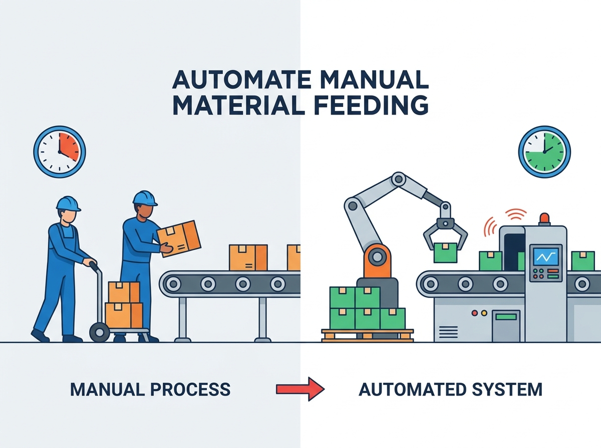
Upgrading these operations requires a complex engineering approach rather than a simple equipment purchase. You must rigorously evaluate material characteristics and plan for existing assembly conveyor integration to achieve consistent dispensing. When you decide to automate manual material feeding, you transform your manufacturing process. You remove the human bottleneck and unlock true production scalability. This transition demands careful planning, precise mechanical selection, and flawless execution.
Baseline Metrics Dictate System Design: Successful automation requires precise documentation of current manual cycle times, error rates, and labor costs to establish accurate ROI and throughput targets.
Material Characteristics Drive Selection: The physical properties of the component (geometry, fragility, abrasiveness) dictate whether a vibratory, robotic, or pneumatic feeding system is viable.
Integration Outweighs Standalone Speed: An automated feeder must synchronize seamlessly with existing PLCs and downstream assembly conveyor systems; isolated speed improvements often just shift the bottleneck.
Risk Mitigation is Mandatory: Transitioning from manual to fully automated lines requires phased commissioning, rigorous safety protocols for bulk loading, and operator upskilling to prevent extended production downtime.
Table of Contents
You must first audit your current manual feeding processes on the floor. Look closely at cycle time variability across different shifts. Human operators naturally slow down as the day progresses. This fatigue causes unpredictable output and makes line balancing impossible. Document your scrap rates caused by misfeeds. Manual loading often results in misaligned components, especially with small or oily parts that are difficult to grip. These errors damage downstream tooling, cause machine jams, and create expensive waste.
Review your ergonomic and safety incident reports. Repetitive lifting, twisting, and placing motions cause strain injuries over time. These injuries lead to workers' compensation claims, absenteeism, and high turnover. Identify the exact threshold for automation justification. Calculate your current production caps. Determine how much product you cannot manufacture simply because you lack the hands to feed the machines. Finding reliable operators remains difficult in the current labor market. When lost production and labor constraints exceed the price of equipment, you must upgrade.
Calculate the true cost of manual feeding before looking at equipment. Do not look only at hourly wages. Include direct labor, turnover expenses, and training time. High turnover means constant retraining, which drains supervisory resources and slows down the entire line. Factor in defect rates caused by human error. Measure your micro-stoppages. A micro-stoppage happens when an operator drops a part, fumbles with orientation, or takes a brief pause. These tiny delays compound over an eight-hour shift and destroy your overall equipment effectiveness.
Define target Key Performance Indicators for the automated system. Establish your required Parts Per Minute (PPM). This number must align with your downstream equipment capacity. Determine your acceptable Mean Time Between Failures (MTBF). High reliability is non-negotiable on a high-speed line. Define your acceptable changeover times. If you run multiple products, the feeder must switch over quickly. Long changeovers negate the speed benefits of automation.
Record baseline cycle times using video analysis to capture true operator speeds.
Quantify the exact number of micro-stoppages per shift and their duration.
Calculate the total cost of scrap generated by manual misloads over a 90-day period.
Define the maximum acceptable footprint for the new equipment based on current floor layouts.
Establish the target PPM required to keep the downstream assembly machine running at 100% capacity.
Bowl feeders remain the industry standard for orienting bulk components. They use electromagnetic coils and leaf springs to generate precise vibrations. These vibrations move parts up a spiral track machined into the inside of a bowl. Tooling on the track, such as wiper blades, air jets, and cutouts, rejects incorrectly oriented parts back into the center. Only correctly positioned components exit the bowl. Centrifugal feeders use a spinning mechanical disc to push parts outward. They rely on fixed mechanical tooling on the outer rim to orient the components as they exit at high speeds.
Evaluate their best use cases carefully. Bowl feeders excel at high-volume production. They handle uniform, non-fragile parts perfectly. Screws, dowel pins, stamped metal brackets, and robust plastic clips are ideal candidates. However, you must understand their physical limitations. Vibratory bowls generate significant ambient noise, often requiring sound-deadening enclosures. They lack flexibility during product changeovers. You cannot easily adjust a bowl built for an M4 screw to run an M8 screw. You usually need a dedicated bowl for each unique component family.
Step feeders elevate and orient parts directly from a floor-level bulk hopper. They use reciprocating metal plates to lift components step by step. Parts fall into the correct orientation as they move upward due to the geometry of the lifting plates. Incorrectly oriented parts simply fall back into the hopper. Once oriented at the top, parts move onto a linear assembly conveyor system. This linear track transports them directly into the downstream machine escapement. Step feeders integrate seamlessly into existing linear lines and keep the bulk weight low to the ground.
Consider step feeders for difficult or heavy materials. They handle heavy steel billets and large castings easily. They work exceptionally well for cylindrical components like shafts, tubes, or bearing rollers. Step feeders handle abrasive materials much better than vibratory systems. Vibratory bowls degrade quickly when running abrasive cast parts because the constant rubbing wears down the precision tooling. Step feeders operate gently. They prevent part damage and generate much less noise than vibratory bowls, improving the working environment for nearby operators.
Vision-guided robotics represent the peak of flexible material handling. These systems pair high-resolution 2D or 3D vision cameras with robotic arms. You can use SCARA, Delta, or 6-axis robots depending on the required reach and payload. The camera identifies the part's location and orientation on a flat, backlit conveyor belt. The software calculates the exact coordinates and rotation. The robot arm picks the part on the fly and places it precisely into the assembly nest. This entirely eliminates the need for complex, dedicated mechanical tooling.
This technology shifts your floor from fixed automation to flexible automation. It is ideal for high-mix, low-volume manufacturing environments. You can run dozens of different parts on the same system. You simply change the software recipe and swap the robot's end-of-arm tooling. You do not need to buy a new bowl feeder for every new product launch. Vision systems handle complex geometries easily. They adapt instantly to slight variations in part dimensions, flash from molding, or oily surfaces that would jam a mechanical feeder.
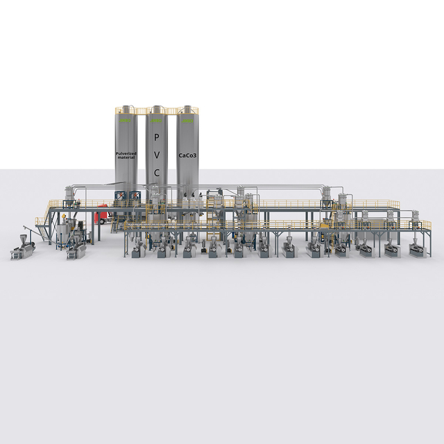
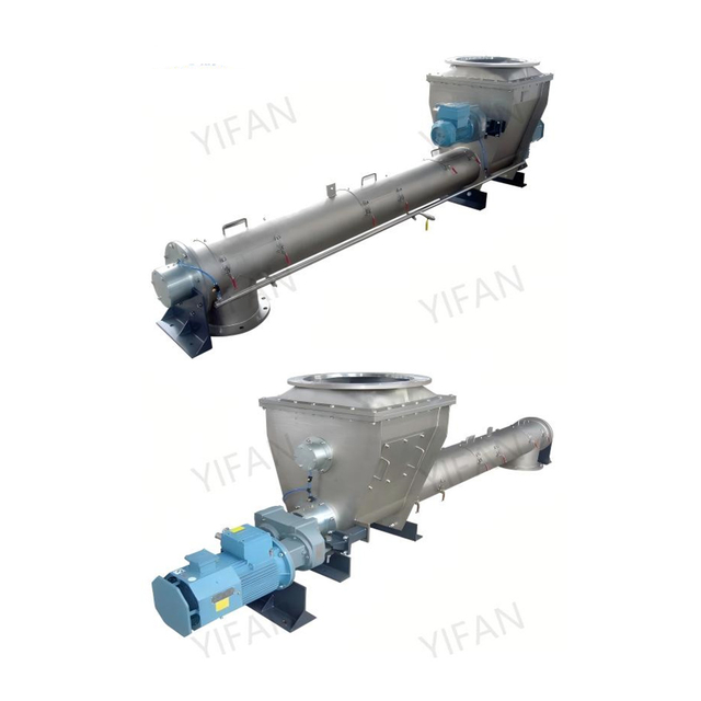
Pneumatic and vacuum systems transport materials using air pressure differentials. Vacuum conveyors pull materials through enclosed tubes using a vacuum pump at the destination. Pneumatic transport pushes materials using compressed air from the source. These systems handle powders, granules, and lightweight flat components. They keep materials completely enclosed during transit. This prevents cross-contamination and stops hazardous dust from escaping into the factory environment. Enclosed transport is mandatory for food processing, pharmaceutical manufacturing, and chemical applications.
These systems excel in specific industrial applications. They are perfect for automating the material loading process for injection molding machines. Vacuum loaders pull plastic resin pellets directly from bulk gaylords on the floor. They feed the resin straight into the molding machine hopper mounted high in the air. This ensures continuous, uncontaminated resin feeds. Operators no longer need to climb ladders carrying heavy bags of plastic pellets. The system runs continuously without human intervention, utilizing level sensors to call for more material only when needed.
You must match the system type to your exact part characteristics. Material geometry dictates the feeding method. Symmetrical parts feed easily and require minimal tooling. Asymmetrical parts require complex orientation tooling to ensure they face the correct direction. Fragility is a major constraint on the floor. You must avoid vibratory bowls for easily scratched cosmetic components, painted parts, or polished medical devices. The constant vibration and part-on-part contact will destroy the surface finish. You must select gentle handling methods, like step feeders or robotics, for delicate items.
Engineering custom tooling requires deep mechanical expertise. Escapements isolate a single part from the continuous feed track. Nests hold the part in the exact position for the downstream operation to pick it up. The design of these components depends entirely on part asymmetry and center of gravity. A slight change in part geometry can render an escapement useless, causing constant jams. You must provide exact, production-grade part samples to your integration partner. They will design the tooling around your specific physical components, accounting for real-world variations like burrs or oil.
Feeder Selection Matrix
Component Profile | Recommended Hardware | Primary Advantage | Hardware to Avoid |
|---|---|---|---|
High-volume, uniform, robust | Vibratory Bowl Feeder | Maximum throughput speed | Robotic Pick-and-Place (too slow) |
Heavy, cylindrical, abrasive | Step Feeder | Gentle handling, low wear | Vibratory Bowl (rapid degradation) |
High-mix, fragile, complex geometry | Vision-Guided Robotics | Ultimate flexibility, no part damage | Mechanical Bowl (inflexible tooling) |
Powders, granules, plastic resins | Vacuum/Pneumatic Conveyor | Enclosed, dust-free transport | Open Belt Conveyors (contamination) |
Line balancing is a critical engineering concept when upgrading. The automated feeder's output must match the downstream machine's consumption rate perfectly. If the feeder is too slow, the assembly machine starves and you lose production. If the feeder is too fast, parts jam at the escapement and cause a fault. You must synchronize these speeds using variable frequency drives and sensor feedback. This synchronization streamlines overall operations. It prevents bottlenecks from simply shifting from the manual operator to the new machine.
You must install inline accumulation buffers. Accumulation provides a physical buffer of oriented parts between the feeder and the assembly machine, usually on a linear vibratory track or conveyor. It prevents micro-stoppages from halting the entire production line. If the bowl feeder jams for ten seconds, the assembly machine continues running using parts from the accumulation buffer. Once the jam clears, the feeder runs slightly faster to refill the buffer. This cascade control guarantees continuous downstream production.
Calculate the exact cycle time of the downstream assembly machine under full load.
Design the feeder to run 15-20% faster than the downstream consumption rate to allow for buffer recovery.
Install linear tracks long enough to hold at least two minutes of accumulated parts.
Use optical sensors on the accumulation track to toggle the feeder on and off automatically.
Implement auto-purge sequences to clear minor jams without operator intervention.
Examine the spatial realities of your factory floor before ordering equipment. Retrofitting automated feeders into legacy manual workstations is notoriously difficult. Manual workstations are usually compact, designed for a human wingspan. Automated systems require significantly more floor space. You need room for the bulk hopper, the orientation unit, the accumulation track, and the control panel. You must measure your available footprint carefully, accounting for forklift aisles and operator walkways. Sometimes you must rearrange adjacent equipment or move structural columns to fit the new automated system.
Address environmental considerations early in the design phase. Cleanroom compliance requires specific materials. You must use 316L stainless steel, enclosed motors, and FDA-approved belts to prevent particle generation. Washdown requirements demand high IP69K ratings. Food and beverage applications require equipment that withstands high-pressure, high-temperature chemical cleaning every shift. Dust mitigation is crucial for powder feeding. You must install proper ventilation, sealed enclosures, and explosion-proof (ATEX) components if handling combustible dusts.
You must address how the automated system itself is fed. Transitioning away from manual feeding changes the safety dynamics on the floor. Operators no longer handle individual parts. Instead, they handle bulk quantities. Loading massive boxes of heavy metal parts presents new ergonomic risks. You must evaluate the safety of these bulk loading operations. Do not replace a repetitive strain injury in the wrists with a catastrophic lifting injury in the lower back.
Integrate ground-level bulk hoppers. Operators should never climb ladders carrying heavy loads or open boxes. Use automated lift-and-tip systems for large gaylords or steel bins. These hydraulic systems lift the heavy container and dump it into the hopper automatically at the push of a button. Maintain ergonomic load heights for manual box dumping. The loading point should sit between waist and chest height. This protects operators from back strain when replenishing the automated feeder.
You must choose between dedicated and flexible automation based on your production strategy. Dedicated automation uses custom-tooled mechanical feeders. Vibratory bowls and centrifugal feeders are dedicated systems. They offer incredible high-speed efficiency. They process hundreds of parts per minute reliably. However, they lack adaptability. If your product design changes, even slightly, you must often scrap the bowl tooling and buy a new one. Dedicated systems lock you into a specific product design for the life of the equipment.
Flexible automation uses vision-guided robotics and programmable conveyors. This approach offers massive adaptability. You can run completely different products on the same shift. You simply change the robot's end-of-arm tooling and select a new program on the HMI. Analyze the trade-off carefully. Dedicated systems have lower initial capital expenditure and higher raw speeds. Flexible systems have higher initial capital expenditure but much lower future re-tooling costs. Choose based on your product life cycles and expected engineering changes.
Select dedicated automation for products with multi-year lifecycles and zero planned design changes.
Choose flexible automation if you launch new product variations every few months or run high-mix batches.
Evaluate the physical space; robots often require larger safety enclosures than compact bowl feeders.
Assess your internal engineering skills; vision systems require software programming and lighting knowledge.
Upgrading a manual production line requires a phased approach to mitigate risk. Never rush the implementation. Start with an initial site audit. Measure available space, power drops, air supply pressure, and floor vibration. Next, draft a comprehensive User Requirement Specification (URS). The URS defines exactly what the system must do. It details speeds, materials, safety requirements, and acceptable fault rates. The URS holds the vendor accountable for the final performance on your floor.
Move into 3D modeling and simulation. Your integration partner should provide detailed CAD models. Review these models carefully with your maintenance team. Ensure the system fits your floor plan and that operators can reach all maintenance points safely. Simulation software can prove the cycle times and robot reach before any metal is cut. Once you approve the design, procurement and fabrication begin. This phased approach eliminates expensive surprises during installation.
Integrating new automated feeders with legacy controls presents significant technical risk. The new feeder must talk to your existing assembly conveyors. This requires precise Programmable Logic Controller (PLC) integration. You must establish clear handshake protocols using 24V DC signals or industrial Ethernet. The downstream machine must tell the feeder when it needs parts. The feeder must tell the downstream machine if it runs empty or faults out. Without this communication, the systems will crash into each other.
Detail the requirements for clear I/O mapping. Every sensor needs a designated input on the PLC. Hopper low-level sensors prevent the system from running dry and starving the line. Jam detection sensors stop the machine before parts get crushed in the escapement. Emergency stop (E-stop) cascading is critical. If an operator hits the E-stop on the assembly machine, the automated feeder must also stop instantly. Hardwire these safety circuits together using dedicated safety relays.
Map all input and output signals between the new feeder and the existing PLC using dry contacts or Ethernet/IP.
Install low-level sensors in the bulk hopper to trigger operator refill alarms via stack lights.
Mount optical sensors on the escapement to detect jams and stop the drive motor immediately.
Wire all E-stop buttons in series to ensure a single press stops all connected machinery simultaneously.
Replacing a human operator with automated moving parts introduces new mechanical hazards. You must follow strict regulatory requirements. Adhere to OSHA, ISO, and RIA standards for machine safety. Automated feeders have pinch points, moving tracks, pneumatic cylinders, and robotic arms. You cannot leave these mechanisms exposed on the factory floor. You must protect your workforce from accidental contact. Compliance is a legal requirement, not an optional feature.
Implement robust machine guarding. Use physical guarding like polycarbonate enclosures or heavy-duty wire mesh fencing. Keep operators away from moving parts during operation. Install safety light curtains across loading zones. If an operator reaches through the light curtain to clear a part, the machine stops instantly. Use safety interlocks on all access doors. If someone opens a maintenance door while the machine is running, the interlock cuts the power and dumps the air pressure immediately.
Installation will disrupt your production schedule. You must manage this downtime carefully. Use a phased implementation strategy. Start with an off-site Factory Acceptance Testing (FAT). Travel to the vendor's facility. Run your actual production parts through the machine for several hours. Verify the speeds, accumulation, and reliability before the machine ships. Fix any mechanical or programming issues at the vendor's shop, not on your factory floor.
Perform Site Acceptance Testing (SAT) after installation. Run the system in your facility under real production conditions, using your plant air and power. Consider parallel running if possible. Keep your manual feeding station operational on a temporary table while testing the automated system. Detail the importance of operator and maintenance training. Train your team on clearing jams, resetting faults, and loading bulk material before the system goes live. A smooth handover prevents extended production downtime and operator frustration.
To successfully automate manual material feeding, manufacturers must prioritize system reliability over theoretical maximum speeds. Consistent dispensing and seamless line integration dictate your ultimate success on the floor. A feeder that runs at 500 parts per minute but jams every hour is useless. Focus on steady, predictable output. Select an integration partner with proven experience handling your specific material types. Ensure they possess in-house controls engineering and offer robust post-installation support.
Take these concrete steps to begin your automation upgrade:
Initiate a comprehensive site audit to measure available floor space, air pressure, and utility connections.
Gather physical part samples, including worst-case variations and oily parts, for vendor feasibility testing.
Draft a detailed User Requirement Specification defining your exact speed, safety, and PLC integration needs.
Calculate your current manual scrap and labor costs to establish a firm baseline for ROI.
With around 20 years of industry experience, Zhangjiagang Yifan Machinery Co., Ltd. integrates R&D, manufacturing, sales, and service, focusing on automatic mixing and feeding systems and intelligent material conveying equipment. Its experience in feeding, pneumatic conveying, weighing, and metering solutions enables the company to support manufacturers seeking more reliable and integrated material handling automation.
A: The typical ROI timeline ranges from 12 to 24 months. This depends heavily on your shift structure. Running three shifts accelerates the ROI significantly compared to a single shift. High local labor rates and severe scrap reduction also shorten the payback period. Systems replacing multiple operators achieve ROI much faster.
A: Yes, delicate materials can be fed automatically. You must avoid aggressive vibratory bowls. Instead, use step feeders or vision-guided robotics. Engineers apply specialized polyurethane coatings to tracks and hoppers. These coatings cushion the parts and prevent surface damage during orientation and transport.
A: Semi-automated handling still requires an operator for specific tasks, like bulk loading or initial orientation. The machine assists the human. Fully automated handling manages the entire process. It moves parts from a bulk hopper, orients them, and places them into the final assembly without any human intervention.
A: Dedicated mechanical systems, like bowl feeders, require swapping custom physical tooling. This takes time and manual labor. Flexible systems, like vision-guided robotics, handle changeovers digitally. You simply load a new software recipe and occasionally swap a robotic gripper. This reduces changeover time from hours to minutes.
A: Sensors immediately detect the jam and stop the drive motor to prevent part damage. Many modern systems feature auto-purge functions. They briefly reverse direction or blast compressed air to clear the blockage automatically. If manual intervention is required, accessible clearing mechanisms minimize the Mean Time To Repair.
A: No, you do not need to upgrade the entire line. You can retrofit automated feeders into existing setups. Integrators use standalone PLC integration to communicate with legacy equipment. They install accumulation conveyors to bridge the speed differences between the new high-speed feeder and older downstream machinery.
A: Operators use ergonomic ground-level hoppers to avoid lifting heavy boxes overhead. Automated bin tippers hydraulically lift and dump large containers safely. Low-level sensors alert operators well before the system runs dry. This ensures safe, scheduled replenishment without rushing or risking physical strain.


