


Views: 0 Author: Site Editor Publish Time: 2026-08-14 Origin: Site


Contamination in automated manufacturing hits hard. A single foreign object or bacterial bloom triggers product recalls, ruins entire batches, wrecks processing equipment, and invites heavy compliance penalties. High-velocity automatic feeding lines hide numerous vulnerabilities. Complex pipe networks, continuous material flow, and enclosed transport mechanisms create blind spots. Physical, chemical, and biological contaminants accumulate and spread unnoticed in these areas. Relying on end-of-line detection fails because it reacts too late. By the time a metal detector kicks out a finished package, your upstream process is already compromised. You lose raw materials and production time. To protect product integrity, we must engineer proactive safeguards directly into the feeding system architecture. You have to implement robust sanitary designs, inline separation, and advanced sensor technologies at the source. This is how you prevent material contamination before it ever reaches the primary processing stream.
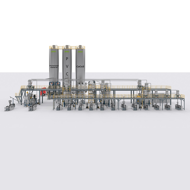
Design dictates defense: Sanitary equipment design, including crevice-free welds and appropriate material selection (e.g., 316L stainless steel), is the baseline for preventing physical and biological buildup.
Integration of separation and detection: Combining inline filtration, magnetic separators, and automated sensors creates a multi-layered defense against foreign materials.
Process controls prevent cross-contamination: Standardized Clean-In-Place (CIP) systems, digital material tracking, and rigorous changeover protocols are critical for multi-product feeding lines.
Compliance is a byproduct of engineering: Aligning system upgrades with FDA, FSMA, and GMP standards mitigates legal and financial risks while ensuring product integrity.
Table of Contents
Contamination in automatic feeding systems falls into three distinct categories. Physical contamination involves tangible foreign objects entering the material stream. You typically see metal shavings from degrading rotary valves, shredded pieces of elastomer seals, loose flange bolts, or external debris like plastic packaging dropping into the hopper. Chemical contamination happens when unintended substances mix with the product. Gearbox seals fail and leak industrial lubricants into the product zone. Operators use the wrong concentration of cleaning agents, leaving a chemical film behind after sanitation cycles. Flaking paint from non-sanitary carbon steel frames also falls into this category.
Biological contamination stems from microbial growth, mold, or pathogens proliferating in stagnant material pockets. This happens frequently in environments with uncontrolled ambient moisture. Bulk material handling and powder feeders specifically exacerbate these risks. Fine powders generate heavy dust. This dust settles on ledges, structural beams, and light fixtures, eventually falling into open processing zones. Powders also bridge and rathole within hoppers. When material bridges, it creates stagnant zones where biological contaminants thrive. Operators often strike the outside of the hopper with a mallet to clear the bridge. This hammering fractures internal scale or degrades welds, sending physical contaminants directly into the product stream.
Mapping critical failure points requires walking the line and following the material path from intake to discharge. You have to look at the physical mechanics of the equipment.
Bulk Silos: Internal wall degradation introduces rust or scale. Improper venting leads to condensation on the silo roof. The condensation drips down into the powder, fostering biological growth on the silo walls.
Rotary Valves: The tight tolerances required for airlocks create a massive risk for metal-to-metal wear. If a rotor deflects under pressure or the outboard bearings fail, the valve shears metal shavings directly into the pneumatic conveying line.
Pipe Connections and Dead Legs: Gasket degradation at flange joints introduces rubber or silicone fragments into the flow. Poorly designed piping networks feature dead legs. A dead leg occurs when a pipe branches off but ends abruptly at a capped tee. Material packs into this blind alley. Ambient moisture turns this packed powder into a hardened plug where bacteria colonize. As fresh product flows past, it shears off microscopic layers of this bacterial colony, contaminating the downstream batch.
Manual Dump Stations: These areas interface directly with the external environment. They are highly susceptible to airborne dust, stray packaging materials, and debris introduced by operators. A worker might drop a utility knife or a pen into the grate during the loading process.
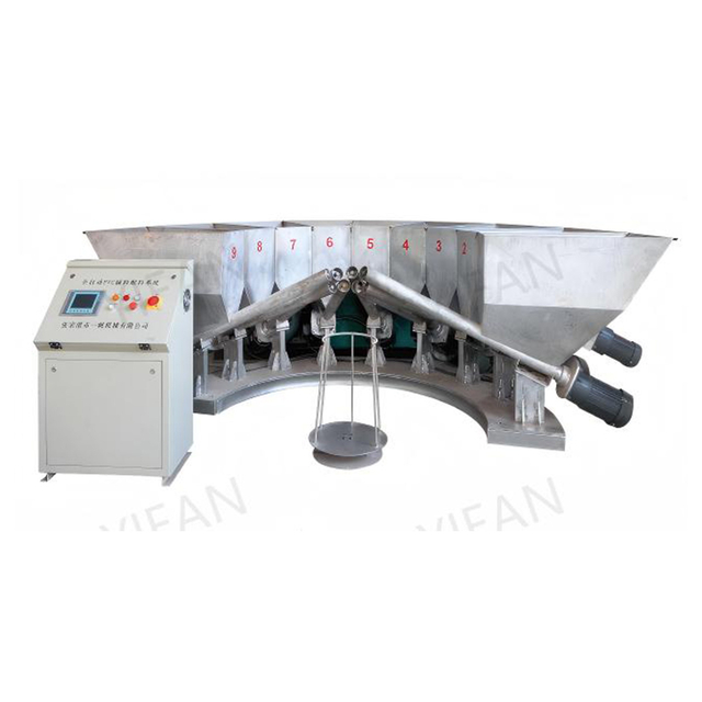
Preventing contamination starts with the physical construction of the feeding equipment. Sanitary design requires eliminating any feature that harbors bacteria or traps foreign particles. Internal surfaces must have a smooth finish. We typically specify an Ra (Roughness Average) value of 0.8 micrometers (32 microinches) or lower. All joints must utilize continuous TIG (Tungsten Inert Gas) welding. Welders must grind these joints smooth and polish them to remove all porosity. Internal threads, sharp corners, and overlapping joints are strictly prohibited in sanitary environments. If a bolt is required inside the product zone, it must be an acorn nut to prevent material from packing into exposed threads.
Material selection dictates durability and cleanability. Standard carbon steel rusts and flakes, making it unacceptable in sanitary feeding lines. The industry relies heavily on specific grades of stainless steel and approved elastomers.
Alloy and Polymer Specifications for Sanitary Environments
Substance Grade |
Physical Characteristics |
Primary Application in Feeding Lines |
|---|---|---|
304 Stainless Steel |
Good corrosion resistance, highly formable, standard sanitary grade. |
Dry bulk handling, external framing, standard hoppers, and pneumatic piping. |
316L Stainless Steel |
Superior corrosion resistance due to molybdenum content; low carbon prevents weld decay. |
Wet processing zones, CIP environments, highly acidic or salty material contact surfaces. |
FDA-Approved Elastomers (EPDM, Silicone, PTFE) |
Non-toxic, resistant to chemical degradation, withstands high washdown temperatures. |
Flange gaskets, rotary valve seals, flexible transition sleeves, and sight glass mounts. |
Isolating the product stream from the surrounding facility environment is a fundamental defensive strategy. Closed-loop pneumatic or mechanical conveying systems ensure that once material enters the line, it remains completely enclosed until discharge. This architecture stops airborne dust, facility debris, and external moisture from compromising the batch. You have to look at the conveying velocity as well. Dilute phase pneumatic conveying moves material at high speeds, which aggressively erodes pipe elbows. This erosion introduces metal dust into the product. Switching to dense phase conveying moves the material slower and in slugs, drastically reducing pipe wear and physical contamination.
Implementing positive pressure systems within these enclosed architectures adds an extra layer of security. By maintaining a slightly higher air pressure inside the conveying line compared to the external environment, any microscopic leaks push clean air out rather than allowing contaminated facility air in. At material intake points where the system opens to the environment, engineering controls take over. Integrating localized exhaust ventilation (LEV), dedicated dust hoods, and physical barriers shields the product stream. These systems capture airborne particulates before they settle into the hopper.
Mechanical safeguards sit strategically throughout the material flow to capture contaminants that bypass initial defenses. Inline screens and vibratory sifters scalp oversized particles, clumps, and foreign debris from powders and granular materials. Install these immediately after bulk discharge points and prior to critical processing equipment like mills or extruders.
Magnetic separation captures ferrous metal, work-hardened stainless steel fragments, and rust. Standard ceramic magnets lose their pull over time. You need rare-earth neodymium magnets pulling at least 10,000 Gauss. Configure these as staggered grates inside hopper throats, inline traps in pneumatic lines, or magnetic tubes in gravity-fed chutes. When material falls through, it must hit a magnetic tube. Maintenance teams must pull and clean these grates daily. A magnet covered in iron fuzz loses its effectiveness because the magnetic field cannot penetrate the buildup.
Automated detection systems act as the final verification step within the feeding architecture. Gravity fall metal detectors sit in vertical pipe sections, inspecting free-falling bulk powders or granules. When these systems detect a conductive or magnetic anomaly, they trigger automatic rejection mechanisms. A high-speed diverter flap or Y-valve rapidly redirects the contaminated portion of the material flow into a reject bin. The rest of the production line continues without halting.
X-ray inspection systems offer broader detection capabilities. They identify non-metallic contaminants such as glass, dense plastics, stones, and calcified bone. Integrating X-ray technology into a feeding line requires careful consideration of material presentation. The product must pass through the beam in a uniform, shallow layer for accurate density analysis. If the powder bed is too thick, the X-ray cannot distinguish a small stone from a dense clump of product.
Inline Inspection Technology Capabilities
Technology Type |
Target Contaminants |
Operational Limitations |
Ideal Placement |
|---|---|---|---|
Gravity Fall Metal Detectors |
Ferrous, non-ferrous, and stainless steel fragments. |
Struggles with wet or highly salty materials due to conductive product effect. |
Vertical pipe sections immediately after bulk discharge or before packaging. |
X-Ray Inspection |
Glass, stones, dense plastics, calcified bone, metal. |
Cannot detect low-density plastics, thin films, or rubber gasket shreds. |
Flat conveyor belts or shallow gravity chutes where material presentation is uniform. |
Optical Sorters |
Discolored product, foreign organic matter, distinct plastics. |
Requires clear line of sight; ineffective in dense powder flows. |
Granular or pelletized material lines prior to final milling. |
Modern powder supply systems utilize advanced sensor networks to identify contamination risks before they escalate. Foreign matter detection sensors use optical or acoustic technology to spot anomalies in the powder flow. Flow monitoring sensors detect blockages or bridging, alerting operators to potential stagnation zones where biological contamination develops.
Predictive maintenance sensors prevent self-generated physical contamination. Install vibration and temperature sensors on the bearings of rotary valves, screw feeders, and blower motors. Maintenance teams monitor equipment health in real time. A spike in vibration often precedes a bearing failure or rotor deflection. Operators replace the worn component before it sheds metal shavings into the product stream.
No detection technology is flawless. You have to navigate the trade-offs between sensitivity and operational efficiency. High sensor sensitivity increases the likelihood of catching microscopic contaminants but simultaneously raises the risk of false rejects. Excessive false rejects waste valuable raw material and disrupt production flow. Operators get frustrated and turn the sensitivity down, defeating the purpose of the machine.
Specific technologies have inherent limitations. X-ray systems struggle to detect low-density plastics or thin films because their density matches the surrounding organic material. Metal detectors suffer from "product effect" when inspecting wet, salty, or highly conductive materials. The moisture and salt create a conductive signal that mimics metal. Operators reduce the detector's sensitivity to stop the false trips, which increases the risk of smaller metal fragments passing through undetected.
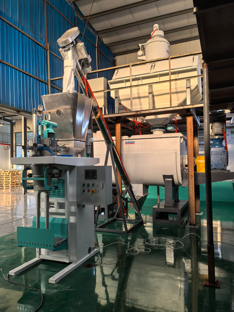
Human error during the loading phase causes massive cross-contamination, particularly when operators introduce incompatible ingredients or allergens into the wrong feeding line. Implementing strict digital tracking at the intake phase eliminates this risk. Facilities utilize barcode scanning or RFID tagging on all incoming bulk bags and raw material containers.
Operators scan the material before loading it into the dump station. Automated recipe-matching software verifies the scanned code against the active production schedule. If an operator attempts to load the wrong ingredient, the control system physically locks the intake grate or disables the rotary valve. This hard interlock prevents accidental mixing and ensures absolute batch integrity.
Maintaining hygiene in feeding lines requires rigorous sanitation protocols. Manual Clean-Out-of-Place (COP) processes require operators to disassemble pipework, valves, and hoppers. They transport the parts to a washroom, clean them manually, and reassemble the line. This method destroys equipment. Operators drop heavy stainless parts on the floor, denting sanitary flanges. They use abrasive pads that scratch the Ra 0.8 finish, creating microscopic grooves where bacteria hide.
Automated Clean-In-Place (CIP) systems are vastly superior for complex feeding architectures. CIP systems circulate water, detergents, and sanitizers through the enclosed feeding line without requiring disassembly. To ensure repeatable hygiene and prevent material contamination from biological sources, CIP systems rely on precise engineering controls. You pump caustic wash at velocities above 1.5 meters per second to create turbulent flow. The turbulence scrubs the pipe walls mechanically. You must engineer the spray balls correctly to ensure they hit every internal surface, leaving no shadow zones unwashed. You follow with a sanitizing rinse and a hot air purge to dry the line completely.
Multi-ingredient lines demand strict engineering controls during product changeovers to prevent cross-contamination between batches. This is non-negotiable when handling major allergens. Facilities implement automated purging sequences that utilize high-pressure air or inert gas to clear residual material from the pneumatic lines and feeder housings.
Physical tools and utensils used around the intake stations must be color-coded and dedicated to specific ingredients to prevent cross-contact. You do not use the peanut scoop in the flour bin. Following a changeover and sanitation cycle, quality assurance teams execute verifiable swab-testing protocols. They utilize ATP (Adenosine Triphosphate) swabs or specific allergen test kits on the equipment surfaces. This confirms the line is entirely free of residue before the next batch begins.
Automated sensors and CIP systems do not eliminate the need for manual verification. Routine visual audits inspect areas that sensors cannot monitor. Maintenance personnel follow strict protocols for inspecting the physical condition of the equipment between major production runs.
Inspectors use high-lumen flashlights to examine the exterior of silos and pipework for signs of structural fatigue, cracked welds, or moisture ingress. Borescopes are mandatory for inspecting the inside walls of silos, hidden pipe connections, and internal feed transport mechanisms. These visual checks confirm the absence of residual buildup, identify degrading seals, and verify that CIP spray balls are functioning correctly without blockage.
Upgrading feeding equipment is a regulatory necessity. The Food Safety Modernization Act (FSMA), FDA regulations, and Good Manufacturing Practices (GMP) mandate strict preventive controls. Facilities prove they have identified potential hazards and implemented verifiable systems to mitigate them.
Documented contamination prevention measures satisfy auditor requirements for Hazard Analysis and Critical Control Points (HACCP). You hand the auditor sanitary design certifications, automated reject logs from the metal detectors, and validated CIP cycle reports. When a feeding line is engineered for compliance, it transforms regulatory audits from high-stress events into routine verifications.
Calculating the return on contamination prevention systems requires looking at risk exposure. The upfront capital expenditure for 316L stainless steel construction, rare-earth magnets, and inline X-ray systems is significant. You contrast this cost against the catastrophic financial impact of a contamination event.
A single product recall involves the cost of retrieving the product, destroying the contaminated batch, paying compliance fines, and managing severe brand damage. Unplanned downtime caused by equipment failure or extensive manual deep-cleaning destroys production efficiency. Investing in proactive engineering controls ensures continuous uptime, protects brand equity, and eliminates the financial liabilities associated with contaminated product reaching the consumer.
Integrating modern sanitary components and advanced sensors into older, existing feeding lines presents complex engineering challenges. Legacy systems feature non-standard pipe diameters, obsolete control architectures, and space constraints that make installing new inline detectors difficult.
Facilities conduct thorough system audits before purchasing new equipment. Engineering teams utilize 3D laser scanning to map the existing facility layout, ensuring new components fit the physical space. You utilize custom transition fittings and sanitary spool pieces to allow new sensors or magnetic traps to mate seamlessly with older pipework. Phasing the upgrades helps manage capital costs. You start with high-risk intake zones before modifying discharge points.
Installing new prevention systems requires taking the feeding line offline. This directly impacts production schedules. Minimizing this disruption requires meticulous project management and strategic installation techniques.
Modular installation is the standard approach. Installation teams pre-fabricate pipework, pre-wire sensor arrays, and assemble diverter valves off-site. This drastically reduces the time required on the factory floor. Facilities schedule the physical integration of these modules during planned facility shutdowns or routine maintenance windows. This ensures the upgrade process does not interfere with peak production demands.
Take the following actions to secure your production lines:
Conduct a comprehensive contamination risk assessment of your current feeding lines, mapping every intake, valve, and discharge point.
Consult with specialized material handling engineers to identify areas where sanitary design principles are currently failing.
Request pilot testing for new separation and detection technologies using your specific bulk materials to verify sensitivity and flow rates.
Implement digital tracking at all manual dump stations to immediately halt cross-contamination errors.
Building a safer feeding line requires contamination control to be considered across material intake, mixing, conveying, metering, cleaning, and system monitoring rather than relying on a single inspection point. Zhangjiagang Yifan Machinery Co., Ltd. integrates R&D, manufacturing, sales, and service for automatic mixing and feeding systems and intelligent material conveying equipment, with solutions including centralized feeding, pneumatic conveying, mixing, weighing, and metering equipment that can support more integrated material-handling workflows.
A: The most frequent cause is internal equipment wear. Degrading elastomer seals, friction within rotary valves, failing pipe connections, and metal fatigue in moving parts introduce rubber fragments and metal shavings directly into the material flow.
A: Prevention requires dedicated conveying lines for major allergens, digital material tracking with barcode labeling at the intake phase, automated CIP systems for thorough sanitation, and rigorous changeover protocols verified by ATP swab testing.
A: Install magnetic separators strategically at all material intake points, immediately before critical processing equipment like mills or extruders, and at gravity free-fall locations to capture ferrous contaminants before they spread downstream.
A: No system is flawless. Inline sensors detect and reject contaminants, but true prevention requires sanitary equipment design and mechanical separation. Sensors have detection limits and serve as a final defense, not a replacement for proactive engineering.
A: Sanitary design utilizes smooth, crevice-free 316L stainless steel, continuous TIG welds, and eliminates internal threads or dead legs. Standard industrial design features exposed threads, overlapping joints, and hard-to-clean corners that harbor bacteria and trap debris.
A: Hygiene requires continuous monitoring via inline sensors, supplemented by scheduled visual inspections between every major batch changeover. Maintenance teams use high-lumen flashlights and borescopes to inspect silos, pipes, and transport mechanisms for residual buildup.


