


Views: 0 Author: Site Editor Publish Time: 2026-08-14 Origin: Site


The transition from isolated, manually operated mixing tanks to fully integrated, automated production lines requires precise synchronization between material feed, batch processing, and discharge. Plant managers often find that disconnected control systems lead to batch inconsistencies, material waste, conveyor bottlenecks, and excessive downtime. Relying on fragmented logic for complex fluid or bulk solid handling introduces unacceptable operational risks on the factory floor. When operators manually jog conveyors or guess mixing times, product quality suffers and mechanical wear accelerates. Implementing a unified material handling PLC control architecture bridges the gap between raw material intake, precise mixing sequences, and final product conveying. This centralized approach ensures repeatable quality and measurable throughput gains. By tying every sensor, motor, and valve into a single processor, you eliminate the guesswork and establish a highly deterministic production environment.
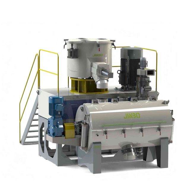
Unified Architecture: Integrating mixing and conveying under a single material handling PLC control system eliminates timing discrepancies and reduces material waste.
Logic Reliability: Sequential ladder logic, supported by robust timers and PID loops, is mandatory for maintaining strict batch consistency and managing variable material viscosities.
Scalability & I/O: Selecting a PLC with modular I/O and standard industrial protocols (PROFINET, EtherNet/IP) is critical for future line expansions and HMI integration.
Risk Mitigation: Successful implementation requires rigorous Factory Acceptance Testing (FAT), hardwired fail-safes, and precise sensor calibration to prevent overflow and equipment damage.
Table of Contents
Establish the baseline metrics for evaluating a successful automation upgrade. You cannot improve what you do not measure. Before writing a single line of ladder logic, facilities must quantify their current operational pain points. We look at specific, measurable data points to define the functional design specification.
Cycle Time Reduction: Measure the total duration from the first ingredient entering the weigh hopper to the final product leaving the discharge conveyor.
Batch Yield Consistency: Track the exact weight of usable product per cycle. This highlights material lost to bridging, spills, or inaccurate manual dosing.
Energy Efficiency: Monitor the power draw of high-torque mixer motors and conveyor drives. Motors should only run when actively processing material.
Operator Intervention Rates: Count how many times a technician must manually jog a belt, clear a jam, or acknowledge a nuisance alarm during a standard shift.
Defining these parameters ensures the programming phase targets specific production outcomes rather than just making motors spin.
Interlocking infeed conveyors or pumps with the mixing tank’s real-time capacity is a hard requirement. A programmable logic controller evaluates the available volume within a mixing vessel before commanding upstream equipment to deliver raw materials. This synchronization relies on continuous data streams from load cells and level sensors. If a bulk solid conveyor runs faster than the mixer's intake rotary valve can process, material bridges in the chute or spills onto the floor. The logic dynamically adjusts the Variable Frequency Drive (VFD) speeds of the infeed conveyors based on the real-time weight accumulation inside the tank. We use a PID loop to taper the conveyor speed as the tank approaches its target weight, ensuring a smooth, continuous feed that matches the recipe's exact dosing profile without overshooting.
Once a batch reaches its required consistency, temperature, and volume, the system hands off the finished material to downstream filling, bottling, or extrusion lines. The control architecture prevents upstream backups or material degradation during this transfer. If the downstream packaging line faults or pauses, the PLC immediately halts the discharge pump. Depending on the material, the logic might initiate a slow agitation cycle to keep the product from settling or curing inside the tank. This requires robust handshaking logic between the mixing controller and the packaging line controller. We utilize dry contact permissive signals over a network protocol to confirm downstream equipment is powered, empty, and ready to receive the product before opening the discharge valve.
Adherence to industry-standard evaluation lenses for batch reporting and traceability is mandatory for modern manufacturing, particularly in food, beverage, and chemical sectors. The ISA-88 standard provides a universal framework for batch control, defining specific equipment models and procedural states like Idle, Running, Held, and Aborted. Programming the system according to ISA-88 ensures that every phase of the mixing and conveying process is strictly documented. The system automatically generates batch logs detailing the exact quantity of each ingredient dosed, the duration of the agitation cycle, and any alarms triggered during the process. We push this data to an SQL database. This historical data supports regulatory compliance and rapid root-cause analysis in the event of a product recall or quality audit.
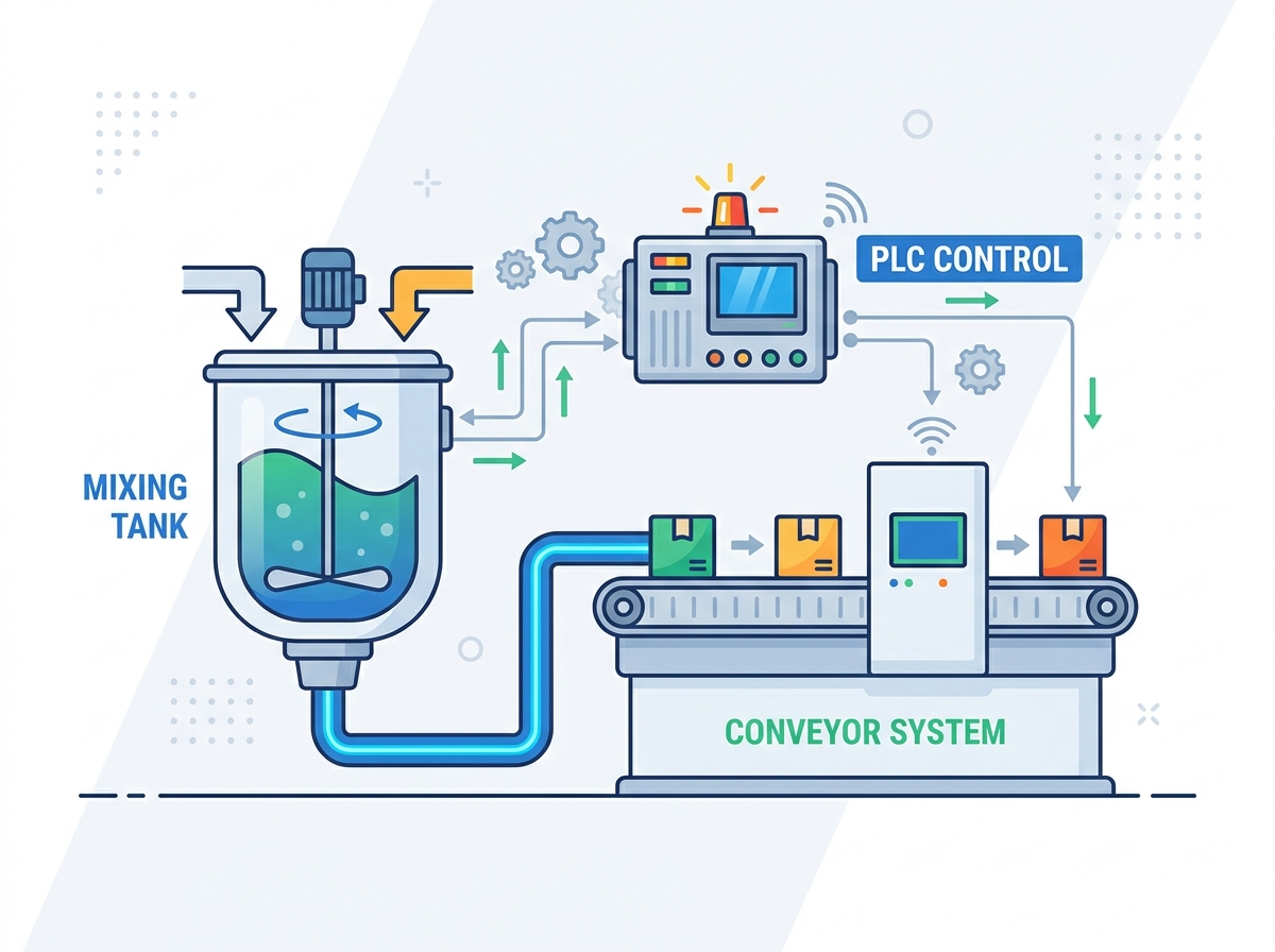
Physical sensors act as the eyes and ears of the control system. Their accuracy dictates the ultimate accuracy of the batch. Load cells mounted under mixing tanks offer high-resolution weight data. We install specialized summing junction boxes to filter out mechanical vibration from the agitator motor before the millivolt signal reaches the PLC analog input card. Level sensors are selected based on material characteristics. Guided wave radar works well for liquids that foam, while ultrasonic sensors handle stable fluids or specific bulk solids. Flow meters provide volumetric verification for liquid dosing. Manual operator inputs remain necessary. Physical push-buttons, emergency stops, and selector switches for auto/manual mode overrides wire directly into the input modules. This allows operators to take localized control during maintenance or abnormal process conditions without bypassing safety interlocks.
Output devices translate the programmed logic into physical mechanical action. Variable Frequency Drives (VFDs) manage conveyor speeds and control the acceleration and deceleration ramps of high-torque mixer motors. Ramping the speed prevents mechanical shock to the drive shafts and gearboxes. For complex dosing, we deploy multi-inlet solenoid valve manifolds. These manifolds require fast-acting digital outputs to open and close pneumatic valves within milliseconds, ensuring precise material cut-offs. Discharge pumps, whether centrifugal or positive displacement, operate with strict interlocks to prevent dry-running. The selection of output modules depends entirely on the voltage and current draw of these specific actuation devices. Transistor outputs handle high-speed switching for PWM signals, while relay outputs manage heavier contactor coils.
Comparing hardware tiers is a foundational engineering decision. Platforms like the Siemens S7-1500 or Allen-Bradley CompactLogix handle complex, high-speed sequential logic and extensive network integration. When selecting the central processor, scan time requirements dictate the choice. A system managing rapid conveyor sorting and high-speed flow meters requires scan times under 5 milliseconds to prevent missed sensor pulses. Memory capacity must store dozens of complex recipes and handle the overhead of state-machine programming. Modular I/O scalability matters just as much. The chosen backplane must allow for the future addition of analog input cards or specialized communication modules without requiring a complete processor replacement. We always specify chassis with at least 20% spare slot capacity for future expansion.
The structural design of ladder diagrams for multi-stage tank mixing requires a disciplined approach. Linear coding, where rungs execute sequentially from top to bottom based solely on physical inputs, becomes unmanageable in complex batching operations. Engineers employ state-machine programming. This method divides the entire mixing and conveying process into distinct, isolated states. Examples include Initialization, Dosing Ingredient A, Heating, Agitating, and Discharging. The logic only executes the rungs associated with the active state. Transitioning from one state to the next requires specific conditions to be met, such as a target weight achieved or a valve confirmed closed via a limit switch. This framework simplifies troubleshooting. Maintenance personnel can immediately identify exactly which step the sequence is waiting on by looking at the active state integer.
Handling multiple inlet valves requires logic that ensures precise sequential or simultaneous dosing based on stored recipe parameters. When dosing sequentially, the logic accounts for material in-flight. This is the amount of product that has passed the valve but has not yet hit the load cells. The program issues a pre-act command to close the dosing valve slightly before the target weight is reached. For high-accuracy applications, we use a bulk-and-dribble sequence. The valve opens 100% for the bulk of the dose, then pulses or throttles down to 10% for the final few pounds. Real-time load cell feedback continuously compares against the active recipe data block, triggering alarms if dosing tolerances exceed acceptable limits.
Specific logic instructions manage the temporal and dynamic aspects of the process. Timers manage agitation durations, settling phases, and provide debounce logic for physical sensors. A debounce timer prevents false triggers from splashing liquids hitting a float switch. Counters track the number of completed batches or the operational cycles of specific valves for preventative maintenance scheduling. Proportional-Integral-Derivative (PID) loops handle continuous, dynamic control. In mixing applications, PID instructions monitor the tank temperature via thermocouples and continuously modulate steam or chilled water valves to maintain a precise setpoint. Tuning these PID parameters requires field experience to prevent temperature overshooting, which degrades sensitive raw materials.
The logic required to prevent material collisions or starvation relies on strict interlocking sequences. Upstream conveyors never start unless the downstream conveyor is already running and confirmed to be at the correct operational speed via a zero-speed switch. This cascading start sequence prevents material from piling up at transfer points. Conversely, a cascading stop sequence ensures that upstream equipment halts first, allowing downstream conveyors to clear their belts before shutting down. Permissive signals, generated by photo-eyes or proximity sensors along the conveyor route, safely initiate these sequences. If a jam is detected, the logic instantly halts all upstream material flow while triggering a localized alarm for operator intervention.
The choice of network architecture dictates how efficiently the mixing station communicates with plant-wide Supervisory Control and Data Acquisition (SCADA) systems and remote I/O racks. Different protocols offer varying levels of speed, determinism, and hardware compatibility. Evaluating these trade-offs ensures the infrastructure handles the required data bandwidth without dropping critical control packets.
Table: Industrial Communication Protocols Comparison
Protocol |
Network Topology |
Real-Time Performance |
Typical Application |
|---|---|---|---|
Modbus TCP |
Star / Tree |
Moderate (Non-deterministic) |
Basic sensor data collection, legacy system integration, non-time-critical monitoring. |
EtherNet/IP |
Star / Ring / Linear |
High (Standard industrial speed) |
VFD control, complex PLC-to-PLC interlocking, standard North American automation. |
PROFINET |
Star / Ring / Line |
Very High (Isochronous Real-Time) |
High-speed motion control, precise valve synchronization, standard European automation. |
IO-Link |
Point-to-Point |
High (Device level) |
Smart sensor parameterization, valve manifold diagnostics, localized data gathering. |
A functional Human-Machine Interface (HMI) serves as the primary tool for operators to interact with the automated system. The design focus remains on diagnostic visibility and process control rather than aesthetic graphics. The HMI provides clear recipe management screens, allowing supervisors to adjust dosing setpoints and timer durations securely behind password protection. Manual jog functions exist on the maintenance screens to allow technicians to bump conveyor motors or cycle individual valves during troubleshooting. Batch completion alarms and fault indicators utilize standard color-coding. Red indicates critical faults that stop the process, while yellow indicates warnings that require attention but allow the machine to run. This ensures operators instantly recognize and respond to process deviations.
Running low-voltage analog signals in high-noise industrial environments introduces significant implementation challenges. Electromagnetic Interference (EMI) from large VFDs and high-voltage motor cables distorts the 4-20mA or 0-10V signals coming from load cells and temperature transmitters. To mitigate this risk, all analog signal cables must be heavily shielded, with the shield grounded at one end only to prevent ground loops. We route high-voltage power cables and low-voltage communication cables in separate grounded conduits. Signal isolation techniques, such as using optical isolators or dedicated signal conditioners in the control panel, protect the sensitive PLC analog input cards from voltage spikes. This ensures the controller receives clean, accurate data for batch processing.
Relying solely on software logic for critical safety functions is an unacceptable engineering practice. Hardwired safety circuits, completely independent of the PLC logic, are a strict necessity. Emergency stop (E-stop) push-buttons and safety pull-cords along the conveyors wire directly into safety relays or a dedicated safety controller. When triggered, these devices physically break the power circuit to the motor contactors and VFDs, bringing all moving equipment to an immediate halt. Overflow prevention in mixing tanks requires redundant, hardwired high-level float switches that cut power to the infeed pumps if the primary analog level sensor fails. Dry-run protection for submersible discharge pumps utilizes hardwired current-sensing relays to prevent catastrophic seal failure.
A structured decision framework for testing prevents costly downtime during the final deployment phase. The Factory Acceptance Test (FAT) occurs at the system integrator’s facility before the control panel ships. This involves connecting the PLC to a simulation rig where toggle switches and potentiometers mimic the physical sensors. Engineers rigorously test edge cases during the FAT. We simulate a load cell failure mid-batch or trigger an E-stop during a critical dosing phase to verify the logic recovers safely. The Site Acceptance Test (SAT) occurs after the hardware is installed on the factory floor. The SAT validates the physical wiring, confirms VFD parameterization, and executes water-batch testing to calibrate flow meters and tune PID loops under actual mechanical load conditions.
A robust control architecture orchestrates the entire material lifecycle from raw infeed to final discharge and downstream filling. By implementing a unified system, facilities eliminate the operational silos that cause batch inconsistencies and mechanical bottlenecks. The success of this integration relies heavily on disciplined state-machine programming, precise sensor selection, and rigorous safety interlocking.
Take the following actions to initiate your automation upgrade:
Conduct an immediate I/O audit of your current mixing and conveying lines to identify failing sensors and unsupported legacy controllers.
Define your Functional Design Specifications (FDS) to clearly outline your required cycle times, batch yield tolerances, and safety interlocks.
Consult with a qualified automation engineer to map out the network architecture and select the appropriate industrial communication protocols for your facility.
Schedule a comprehensive risk assessment to identify necessary hardwired fail-safes and emergency stop zoning prior to finalizing the control panel design.
With 20 years of industry experience, Zhangjiagang Yifan Machinery Co., Ltd. integrates R&D, manufacturing, sales, and service with a focus on automatic mixing and feeding systems and intelligent material conveying equipment. Its experience in mixing, pneumatic conveying, weighing, and related material handling technologies supports manufacturers seeking more integrated, reliable, and scalable automation solutions.
A: The PLC functions as the central industrial computer executing sequential logic based on real-time sensor inputs. It continuously monitors load cells, level sensors, and flow meters, using this data to precisely control output devices like automated valves, high-torque mixers, and discharge pumps according to pre-programmed recipe parameters.
A: It eliminates human error by automating the exact timing and sequencing of material additions. By utilizing load cell feedback and automated dosing via PID loops, the system ensures every ingredient is measured to exact tolerances, resulting in highly repeatable batch quality and significantly reduced material waste.
A: The controller uses sequential valve control and recipe management logic. It opens specific inlet valves one at a time or simultaneously, continuously reading load cell data. Once the precise target weight for an ingredient is reached, the logic instantly commands the valve to close before initiating the next ingredient's sequence.
A: Ladder Logic is the most prevalent due to its visual representation of electrical circuits, making it highly accessible for plant maintenance technicians to troubleshoot. For complex, multi-stage batching operations, Sequential Function Charts (SFC) are often integrated alongside ladder logic to manage state-machine transitions effectively.
A: Overflow prevention requires a multi-layered approach. The primary defense is the PLC logic monitoring analog level sensors. However, redundant, hardwired high-level switches must be installed. If triggered, these switches physically cut power to the infeed pumps via a safety relay, completely bypassing the software logic.
A: Yes, legacy equipment can be retrofitted by installing automated pneumatic valves, adding VFDs to existing motors, and mounting load cells or level sensors. However, the feasibility depends on the mechanical condition of the tank and whether the existing piping can accommodate new automated instrumentation.
A: Sequential control involves batch processing, where the system moves through distinct steps using timers and counters. Continuous control involves inline mixing, where PID loops constantly modulate flow control valves and pump speeds to maintain a steady, uninterrupted ratio of materials flowing through a pipe.


